×
![]()
Test Area 1-120 Test Stand 1-A Description and Photos
Building 8765 is the substructure of Test Stand 1-A . This massive structure is 70 feet wide and 150 feet high at the northern edge and 50 feet wide and 110 feet high at the southern edge, with an overall length of 203 feet from the northern edge to the southern edge. The entire structure is constructed of reinforced concrete. The top deck of the test stand is level with the road in the test area; thus, the structure is primarily subterranean or cantilevered from the northern ridge face. The overall form of the structure is a two-level rectangle between the northern and southern structural piers and a braced cantilevered deck extending from the northern structural pier. A poured concrete, U-shaped deflector pit descends north from the north structural pier at an approximately 60-degree angle from 45 feet below the top deck. The top deck has a hole in the northern end measuring approximately 60 feet wide by 40 feet long. The superstructure above the top deck holds the test vehicle above this opening, directing the blast of the rocket down to the flame deflector pitThe superstructure that holds the test vehicle, the fuel, and the oxidizer has been modified over the years to meet the needs of new testing programs. The current structure is two rectangular, steel, open frames. The southern frame is of lighter steel and supports the fuel and oxidizer tanks on top. The northern frame is of heavier steel and supports the test vehicle in the center of the lower third of the structure. There are two levels of work space below the top deck of Test Stand 1-A in the southern 149 feet of the test stand, referred to as Building 8783. The test stand appears to be in good condition.
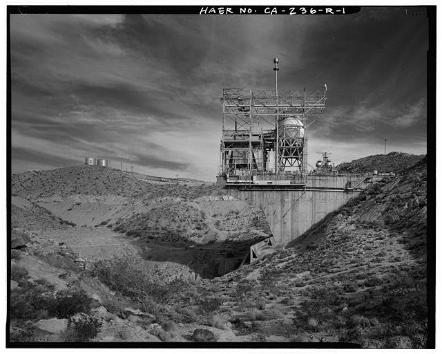
TEST STAND 1-A ENVIRONS, SHOWING WEST SIDE OF TEST STAND 1-A, RP1 COMBINED FUEL STORAGE TANK FARM BELOW WATER TANKS ON HILLSIDE TO LEFT, AND TEST STAND 1-B IN DISTANCE AT RIGHT. Looking east.
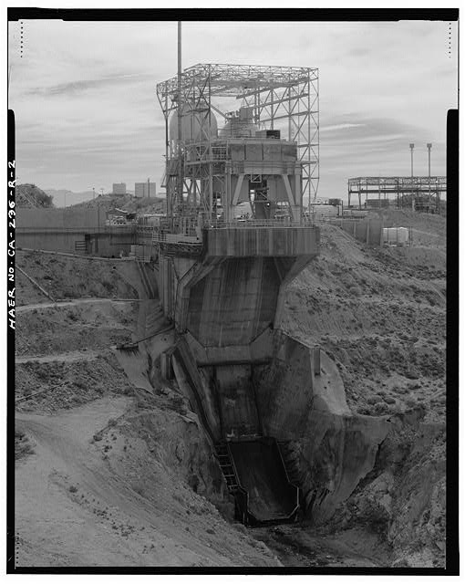
NORTH FRONT, FROM SUPERSTRUCTURE TO FLAME DEFLECTOR. Looking south southwest from Observation Post No. 1 (Building 8767).
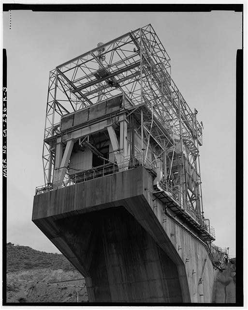
DETAIL OF NORTH FRONT AND WEST SIDE, WITH SUPERSTRUCTURE, FROM NEAR OBSERVATION POST NO. 3. Looking south southeast from below.
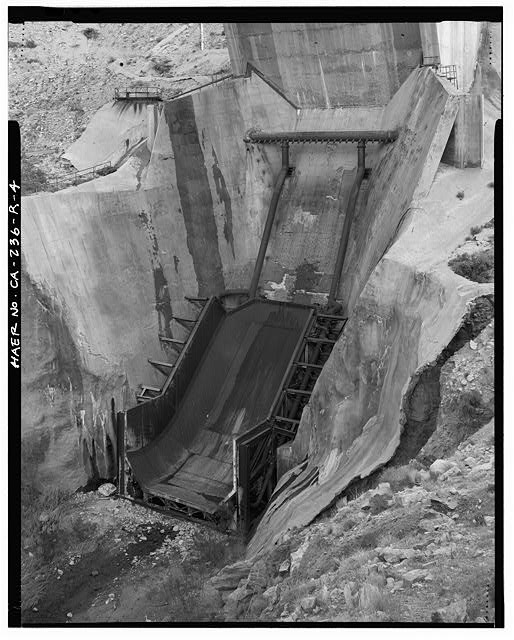
DETAIL SHOWING FLAME DEFLECTOR. Looking southeast.
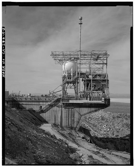
EAST SIDE, TEST STAND AND ITS SUPERSTRUCTURE.
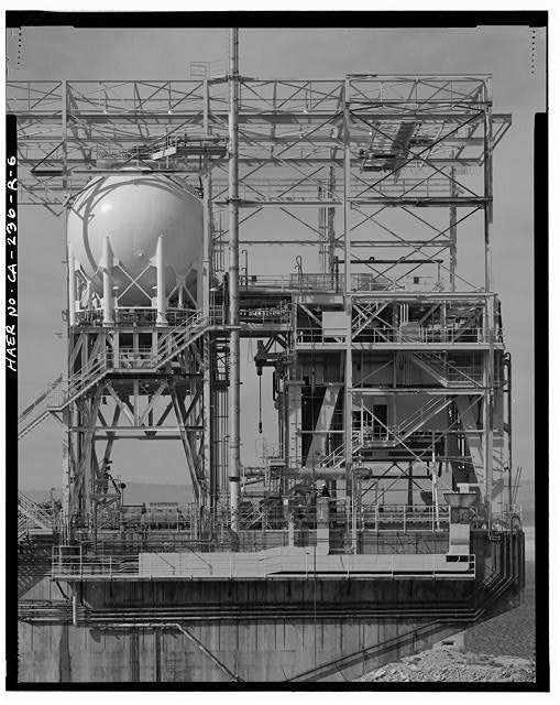
EAST SIDE, SUPERSTRUCTURE.
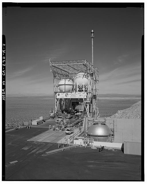
SOUTH REAR. Looking northwest from corner of the Instrumentation and Control Building (Building 8762).
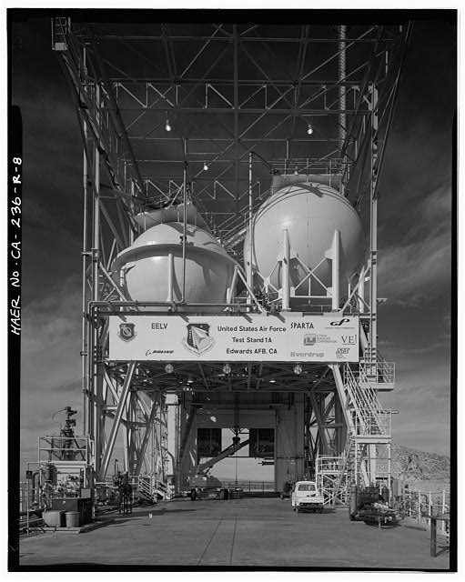
SOUTH REAR, SUPERSTRUCTURE. Looking north from deck.
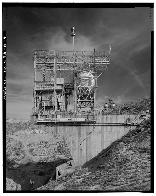
WEST SIDE, TEST STAND AND SUPERSTRUCTURE. TEST STAND 1-B IN DISTANCE. Looking east.
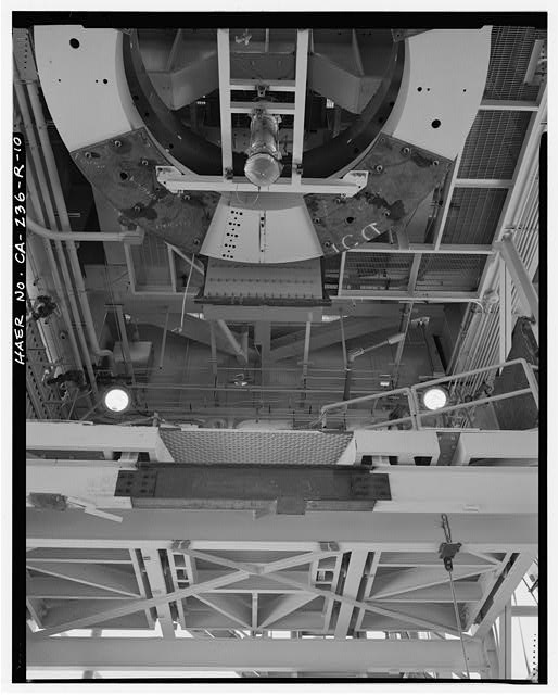
DETAIL SHOWING THRUST MEASURING SYSTEM. Looking up from the test stand deck to east.
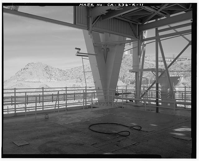
DETAIL SHOWING ROLLING ENGINE DECK AND NORTHEAST TRUSS OF SUPERSTRUCTURE. Looking northeast.
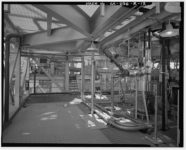
DETAIL SHOWING EAST SIDE OF THE OXYGEN AND HYDROGEN PRE-VALVE DECK (2ND LEVEL). Looking south.
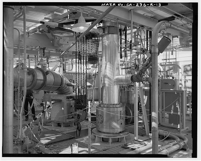
DETAIL SHOWING OXYGEN (LEFT) AND HYDROGEN (RIGHT) PREVALVES ON SECOND DECK OF SUPERSTRUCTURE, ABOVE THE ENGINE. Looking northwest.
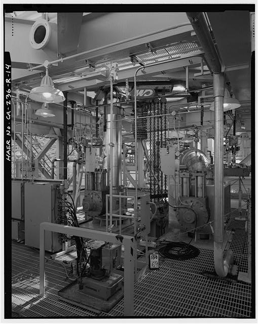
DETAIL SHOWING HYDROGEN (LEFT) AND OXYGEN (RIGHT) PREVALVES. Looking southeast.
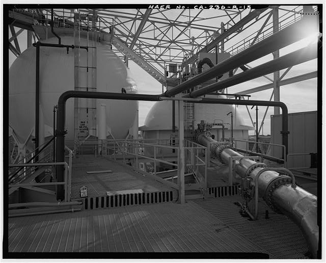
DETAIL SHOWING HYDROGEN (LEFT) AND OXYGEN (RIGHT) SPHERICAL TANKS ON RUN LINE DECK, THIRD LEVEL. DARK TONED PIPING IS THE FIRE EXTINGUISHING SYSTEM. Looking south southwest.
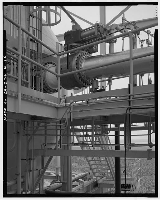
DETAIL SHOWING LIQUID OXYGEN TANK FOURTEEN-INCH BALL VALVE. Looking southwest.
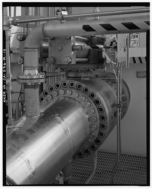
DETAIL, FOURTEEN-INCH LIQUID OXYGEN BALL VALVE. Looking south southeast.
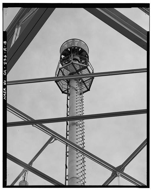
CROWS NEST ATOP SUPERSTRUCTURE. Looking up from northeast corner of run line deck.
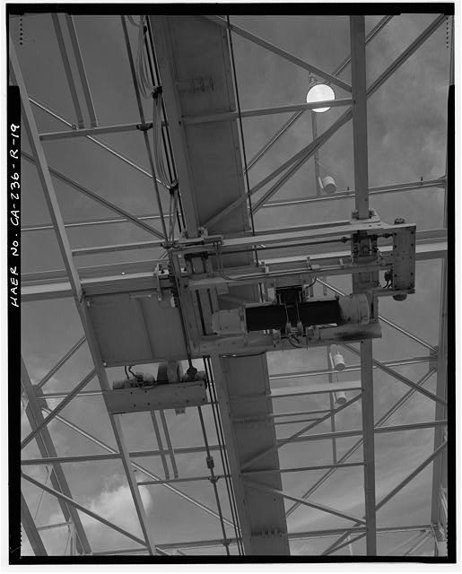
TRAVELING CRANE ATOP SUPERSTRUCTURE, FROM RUN LINE DECK. Looking up to north northeast.
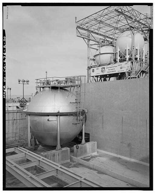
DECOMMISIONED HYDROGEN TANK IN FORMER LIQUID OXYGEN STORAGE AREA, BETWEEN TEST STAND 1-A AND INSTRUMENTATION AND CONTROL BUILDING. Looking northwest.
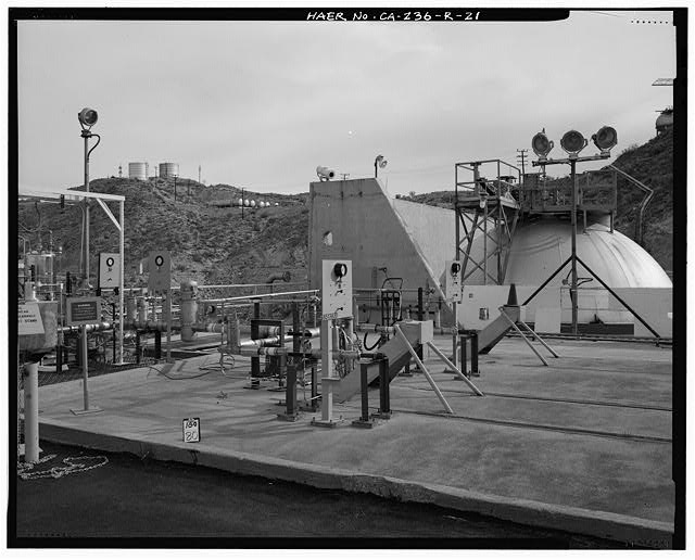
VALVES, GAUGES, AND SEVERAL TYPES OF LIGHTING ALONG ROAD AT SOUTH REAR OF TEST STAND 1-A. RP1 TANK FARM IN MIDDLE DISTANCE. Looking northeast.
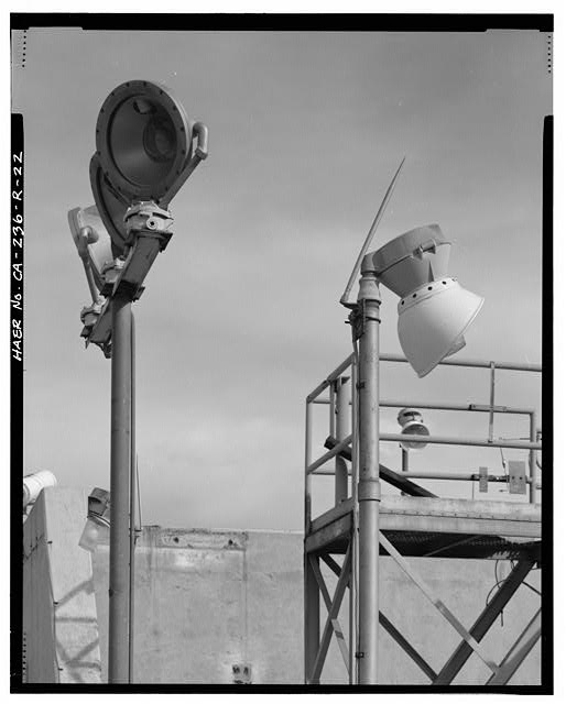
DETAIL, TWO LIGHTING TYPES AT REAR OF TEST STAND 1-A.
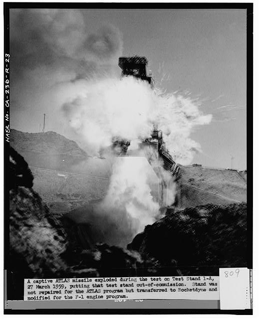
'A CAPTIVE ATLAS MISSILE EXPLODED DURING THE TEST ON TEST STAND 1-A, 27 MARCH 1959, PUTTING THAT TEST STAND OUT-OF-COMMISSION. STAND WAS NOT REPAIRED FOR THE ATLAS PROGRAM BUT TRANSFERRED TO ROCKETDYNE AND MODIFIED FOR THE F-l ENGINE PROGRAM.'
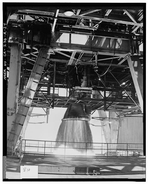
SATURN V F-l ENGINE TEST FIRING ON TEST STAND 1A.
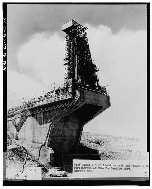
'TEST STAND 1-A UTILIZED TO TEST THE ATLAS ICBM', CROPPED OUT: 'DIRECTORATE OF MISSILE CAPTIVE TEST, EDWARDS AFB.' Photo no. 11,371 57; G-AFFTC 15 OCT 57. Looking southwest from below the stand.